1. Basic concepts: layers and data flow
Layering and encapsulation
| Five-layer teaching model | Responsibility | Examples |
|---|---|---|
| Application | Define how applications exchange information | HTTP, DNS |
| Transport | Transfer data between application endpoints | TCP, UDP |
| Network | Forward packets across networks toward a destination | IP, routing |
| Data link | Deliver frames across an individual link | Ethernet, Wi-Fi link functions |
| Physical | Transmit signals representing bits through a medium | Electrical signals, light, radio waves |
- The seven-layer OSI model adds presentation and session layers between application and transport.
- The four-layer TCP/IP model uses application, transport, internet, and link layers.
Presentation handles encoding and representation; session handles session management. TCP/IP includes these functions in other layers.
Encapsulation adds control information at each layer; decapsulation reverses the process. Unencrypted HTTP over TCP:
Application:                            HTTP data
Transport:                 TCP header + HTTP data
Network:       IP header + TCP header + HTTP data
Link: frame header + IP header + TCP header + HTTP data + trailer
Physical: encode these bits as signals and transmit them
Same-layer peers communicate logically; actual data still travels through lower layers.
LANs, WANs, and access networks
- A LAN, or local area network, connects a limited area such as a home or office.
- A MAN, or metropolitan area network, covers a city-scale area.
- A WAN, or wide area network, connects more distant regions.
- An access network connects users to a provider's network.
Joining Wi-Fi provides access to a wireless LAN, not necessarily to the Internet.
Connection-oriented and connectionless service
| Comparison | Connection-oriented | Connectionless |
|---|---|---|
| Before communication | Establish a connection | No connection establishment required |
| State | Endpoints maintain connection state | Messages are handled independently |
| Examples | TCP | UDP, IP |
| Order and reliability | Depend on the protocol; TCP provides a reliable, ordered byte stream | UDP and IP do not themselves guarantee reliable, ordered delivery |
A TCP connection is state maintained at both ends: sequence numbers, windows, and status. IP packets can arrive out of order; TCP delivers their bytes in order.
Five recurring protocol concerns
| Concern | Meaning |
|---|---|
| Addressing | Identify where data comes from and where it is going |
| Error control | Detect corruption or loss, then correct or retransmit as the protocol specifies |
| Flow control | Keep a sender from overwhelming the receiver's buffers |
| Multiplexing and demultiplexing | Share resources among communications and deliver received data to the correct endpoints |
| Routing | Determine a path toward the destination |
Scope differs: the link layer covers one link; TCP operates end to end.
2. Physical layer: turning bits into signals
Shannon capacity: the limit of a noisy channel
- : theoretical channel capacity, in bit/s.
- : channel bandwidth, in Hz.
- : the ratio of signal power to noise power, expressed as a linear ratio.
Suppose:
Then:
If the signal-to-noise ratio is given in decibels, convert it first:
For example, corresponds to .
Capacity grows linearly with spectral bandwidth and logarithmically with signal-to-noise ratio. Coding and protocol overhead reduce usable throughput.
Units: spectral bandwidth uses Hz; data rate uses bit/s.
Wired and wireless transmission media
| Medium | Characteristics and uses |
|---|---|
| Twisted pair | Copper wires twisted together to reduce interference; common in Ethernet cabling |
| Coaxial cable | A central conductor with shielding; used in systems such as cable television |
| Fiber optics | Carries light, offers high capacity and long reach, and is immune to electromagnetic interference |
| Microwave | Wireless transmission; directional links must account for line of sight and obstructions |
| Infrared | Common in short-range communication, such as remote controls |
| Communication satellites | Broad coverage; propagation delay depends on orbital altitude |
Wavelength and frequency are related by:
is the speed of light in a vacuum; use propagation speed within a medium.
Carrier frequency (Hz) is different from data rate (bit/s).
Frequency, time, and wavelength division multiplexing
- FDM, frequency division multiplexing: separate frequency bands.
- TDM, time division multiplexing: separate time slots.
- WDM, wavelength division multiplexing: different wavelengths in one fiber.
3. Data link layer: framing and reliable delivery
Framing: recognizing boundaries
Framing identifies individual frame boundaries within a bit stream.
| Method | Mechanism | Consideration |
|---|---|---|
| Byte count | Record the frame length | A corrupted length can disrupt boundary recognition |
| Flag bytes with byte stuffing | Mark boundaries with special bytes and escape matching bytes in the payload | The receiver must undo the escaping |
| Flag bits with bit stuffing | Mark boundaries with a bit pattern and alter potentially conflicting payload patterns | The receiver removes the inserted bits |
| Physical-layer coding violations | Use special symbols that cannot occur as ordinary data in the encoding scheme | Depends on the physical encoding |
Bit stuffing: with 01111110 as a boundary, insert 0 after every five consecutive data bits set to 1. The receiver removes it, keeping data from matching the boundary.
Sliding windows: allowing multiple frames in flight
Stop-and-wait:
Send 0 → wait for acknowledgment → send 1 → wait for acknowledgment → …Waiting after every frame wastes transmission time. A sliding window permits multiple frames in flight; with a window of four:
Currently allowed to send: 0, 1, 2, 3

After frame 0 is acknowledged:

The window advances to:    1, 2, 3, 4
Acknowledgments advance the window and allow new data to be sent.
At rate and round-trip time RTT, keeping a link busy requires approximately this much data in flight:
This is the bandwidth-delay product.
Go-Back-N and selective repeat
Suppose the sender transmits:
0, 1, 2, 3, 4, 5and frame 2 is corrupted:
| Behavior | Go-Back-N | Selective repeat |
|---|---|---|
| Receiver gets later frames 3, 4, and 5 | Usually discards them | Buffers them |
| Retransmission | Resends unacknowledged frames starting at the gap | Resends only missing or damaged frames |
| Receiver buffering | Lower | Higher |
| Implementation complexity | Lower | Higher |
| Wasted bandwidth after loss | Higher | Lower |
Selective repeat accepts out-of-order frames but delivers them upward in order after filling the gap.
4. Network layer: addressing, routing, and forwarding
Distance vector: updating routes from neighbors' distances
Each router keeps its cost to each destination and exchanges that information with its neighbors.
For each neighbor , add the cost of reaching it to its reported cost to the destination, then take the minimum.
Candidate routes from J to C:
| Via neighbor | Cost from J to neighbor | Neighbor's reported cost to C | Total |
|---|---|---|---|
| A | 8 | 25 | 33 |
| I | 10 | 18 | 28 |
| H | 12 | 19 | 31 |
| K | 6 | 36 | 42 |
J therefore records:
Destination C: cost 28, next hop ICost can represent hops, delay, or another metric. Stale neighbor reports can cause loops or counting to infinity.
Link state: computing shortest paths from topology
Discover neighbors and link costs → flood link-state information → run Dijkstra on the topology.
Seq. distinguishes newer information; Age helps expire old information.
| Distance vector | Link state |
|---|---|
| Neighbors report their distances to destinations | Routers announce their direct connections and link costs |
| Update routes from neighbors' distances | Compute routes from the topology |
| Common mathematical basis: Bellman-Ford | Common shortest-path algorithm: Dijkstra |
Tunneling: adding an outer encapsulation
Encapsulating IPv6 across an IPv4 network:
Before the tunnel:             IPv6 packet

Across the IPv4 network: IPv4 header + IPv6 packet

After the tunnel:              IPv6 packet
Intermediate routers use the outer IPv4 header; the exit removes it. Encryption depends on the tunneling protocol.
IPv4 header: information needed for forwarding
An IPv4 header is 20–60 bytes.
| Field | Purpose |
|---|---|
| Version | IP version; 4 for IPv4 |
| IHL | Header length in four-byte units; 5 means 20 bytes |
| Total Length | Length of the entire IPv4 packet, including header and data |
| Source / Destination Address | Source and destination IPv4 addresses, 32 bits each |
| TTL | Limits continued forwarding to prevent indefinite circulation |
| Protocol | Identifies the upper-layer protocol, such as 6 for TCP or 17 for UDP |
| Header Checksum | Detects corruption in the IPv4 header |
| Identification, Flags, Fragment Offset | Support fragmentation and reassembly |
| Differentiated Services | Supports functions such as differentiated service and congestion notification |
- Protocol is not a port number: it selects TCP, UDP, or another upper-layer protocol. A transport port then identifies an application endpoint.
- The IPv4 header checksum does not cover the payload.
Fragmentation: DF forbids it, MF indicates more fragments, and offsets use eight-byte units.
IP addresses: from address classes to CIDR
Historical classes: A/B/C used default prefixes /8, /16, and /24; D is multicast and E is reserved.
CIDR uses the explicit /n to identify a network prefix. 127.0.0.0/8 is reserved for loopback. CIDR
For example:
192.168.8.34/24has a 24-bit network prefix and an eight-bit host portion.
Subnets and route aggregation
Consider a /24:
Host address:      192.168.8.34/24
Subnet mask:       255.255.255.0
Network address:   192.168.8.0
Broadcast address: 192.168.8.255
An ordinary /24 broadcast subnet has 256 addresses, typically 254 available to hosts.
The network address is calculated by bitwise AND:
Route aggregation can combine these eight contiguous, aligned /24 prefixes:
192.168.8.0/24
192.168.9.0/24
…
192.168.15.0/24
into a single prefix:
192.168.8.0/21Eight networks require three bits, giving the aggregate prefix length:
The third octet ranges from 8 through 15:
8  = 00001000
15 = 00001111
     └───┘
     First 5 bits match
Shared prefix: 16 + 5 = 21 bits.
Covers 192.168.8.0–192.168.15.255. Route aggregation does not change the original LAN boundaries.
SNAT and DNAT
SNAT example:
Source before translation: 10.0.0.1:5544
Source after translation:  198.60.42.12:3344
Both source address and source port change.
- SNAT changes the source address, commonly for private hosts accessing an external network.
- DNAT changes the destination address, commonly to map a public entry point to an internal server.
A DNAT example is:
External destination: 203.0.113.5:8080
Internal destination: 10.0.0.10:80
The device records mappings and reverses them for return traffic. Address-and-port translation lets private connections share a public IP.
ARP, RARP, and DHCP
ARP resolves an IPv4 address to a MAC address on the local link.
For an external destination, resolve the next-hop gateway's MAC. The frame targets the gateway; the IP packet still targets the remote server.
RARP is a historical protocol for obtaining an IP address from a hardware address.
DHCP configures the IP address, subnet mask, gateway, and DNS server. Its initial DORA exchange:
Discover → Offer → Request → ACK
Find a server → offer settings → request selected settings → confirm assignment
Addresses have leases that need renewal. DHCP
OSPF and BGP
An AS (autonomous system) is a group of networks with a unified routing policy, such as a provider network.
| Protocol | Main role | Main approach |
|---|---|---|
| OSPF | Routing within an autonomous system | Link state, shortest-path computation, areas |
| BGP | Exchanging routes between autonomous systems | Path attributes and routing policy |
BGP selects routes using attributes such as AS paths and administrative policy, not necessarily shortest distance or lowest delay.
5. Transport layer: endpoints, reliability, and sending control
Ports and communication endpoints
IP provides network-layer addressing; ports distinguish application communication endpoints.
A TCP connection is commonly distinguished by a four-tuple:
Source IP, source port, destination IP, destination portFor example:
192.168.1.10:51000 → 203.0.113.20:443
192.168.1.10:51001 → 203.0.113.20:443
Different source ports distinguish these connections, letting one server port serve many connections.
UDP: transmission with message boundaries
A UDP header is always eight bytes, consisting of four 16-bit fields:
| Field | Purpose |
|---|---|
| Source Port | Source port |
| Destination Port | Destination port |
| Length | Total length of UDP header and data |
| Checksum | Error detection |
UDP preserves message boundaries. Upper layers handle loss recovery, ordering, and sending rate as needed.
Uses include DNS, real-time media, and QUIC. Low overhead does not guarantee a faster application.
Common service ports
| Port | Service |
|---|---|
| 21 | FTP control connection |
| 20 | Common server data port for active-mode FTP |
| 22 | SSH |
| 25 | SMTP |
| 80 | HTTP |
| 110 | POP3 |
| 143 | IMAP |
| 443 | HTTPS |
| 554 | RTSP |
| 631 | IPP printing protocol |
These defaults can be reconfigured. IANA port registry
TCP header and byte sequence numbers
A TCP header is at least 20 bytes.
- Sequence Number: the starting byte sequence number of this segment's data.
- Acknowledgment Number: the sequence number the receiver expects next.
- Window: the receive window advertised by the receiver.
- Checksum: checks the TCP header and data, together with pseudo-header information.
- Flags: including SYN, ACK, FIN, and RST.
- Options: such as maximum segment size, window scaling, and timestamps.
TCP sequence numbers count bytes. Suppose a segment carries:
SEQ = 1000
Data length = 500 bytes
The bytes occupy sequence numbers 1000–1499. Once received contiguously:
ACK = 1500ACK identifies the next expected byte, not the last received byte.
TCP has no message boundaries: two send() calls need not match two recv() calls. Applications delimit messages with lengths, separators, or similar mechanisms.
TCP's three-way handshake
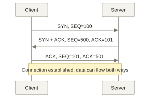
The three-way handshake. Full-size figure · Mermaid source
- The client requests a connection and announces its initial sequence number.
- The server acknowledges the client's number and announces its own.
- The client acknowledges the server's number.
The third message confirms receipt of the server's initial sequence number and prevents old requests from directly creating incorrect connections.
SYN consumes one sequence number, which is why the acknowledgments add one.
TCP closing and half-close
Client → server: FIN, I have no more data to send
Server → client: ACK, your sending direction is acknowledged as finished

The server can still send its remaining data…

Server → client: FIN, I also have no more data to send
Client → server: ACK, your sending direction is acknowledged as finished
Half-close: after sending FIN, an endpoint can still receive data.
ACK and FIN may be combined. FIN and SYN each consume one sequence number.
TCP state machine
Active open:
CLOSED → SYN-SENT → ESTABLISHED

Passive open:
LISTEN → SYN-RECEIVED → ESTABLISHED

Typical active close:
ESTABLISHED → FIN-WAIT-1 → FIN-WAIT-2 → TIME-WAIT → CLOSED

Typical passive close:
ESTABLISHED → CLOSE-WAIT → LAST-ACK → CLOSED- CLOSE-WAIT: the peer sent FIN; the local application has yet to close its sending direction. Long-lived entries can indicate delayed application closure.
- TIME-WAIT: retained state allows acknowledgment of retransmitted FINs and limits interference from old segments.
TIME-WAIT normally lasts 2MSL. MSL is maximum segment lifetime, not RTT. TCP closing
Flow control and congestion control
| Window | Problem addressed | Who determines it |
|---|---|---|
Receive window rwnd | How much data the receiver can accept | Advertised by the receiver |
Congestion window cwnd | How much unacknowledged data the network should carry | Adjusted by the sender from feedback |
Outstanding data is mainly limited by:
Subtract outstanding data to find room for new data. TCP's Window field advertises rwnd; the sender maintains cwnd.
| Phase | Approximate window behavior |
|---|---|
| Slow start | Starts small and roughly doubles per RTT under ideal conditions |
| Congestion avoidance | Switches to roughly linear growth after reaching a threshold |
| Retransmission timeout | Reduces the window substantially and restarts slow start |
| Fast retransmit and fast recovery | Use duplicate acknowledgments to detect likely loss earlier and reduce sending intensity |
Illustrative window growth:
Slow start:           1 → 2 → 4 → 8
Congestion avoidance: 8 → 9 → 10 → 11
The initial value of one is illustrative.
Classic fast retransmit uses three duplicate ACKs to detect likely loss before timeout. Fast recovery reduces the window without returning to slow start every time. TCP congestion control
6. Application layer: DNS and HTTP
DNS namespace
Consider this domain name:
robot.cs.washington.edu.Read it from right to left:
.               Root
edu             Top-level domain
washington      Next domain level
cs              Another domain level
robot           Specific name
The trailing dot denotes the root and is usually omitted. Different levels can be managed separately.
Name resolution uses the hostname within the URL:
https://www.example.com/course?id=19
        └── domain ───┘└─ path and query ─┘
DNS resource records
| Type | Purpose |
|---|---|
| A | IPv4 address for a name |
| AAAA | IPv6 address for a name |
| CNAME | Alias pointing to another name |
| MX | Mail receiving server and preference |
| NS | Authoritative name server for a zone |
| SOA | Zone administration data, including serial number and refresh parameters |
| PTR | Name pointer used in reverse lookups |
| TXT | Text, often used for verification or mail policy |
| SRV | Service location, including target, port, and priority |
SPF policies use TXT records. SPF
DNS queries and caching
With no cached answer, resolving robot.cs.washington.edu can proceed as follows:
- The computer asks its configured recursive resolver.
- The resolver asks a root server and receives information about
.eduservers. - It asks a
.eduserver and learns about servers forwashington.edu. - It follows any further delegation, such as to a server responsible for
cs.washington.edu. - It obtains the answer, returns it to the client, and caches it as allowed.
- The client asks the recursive resolver to obtain a result on its behalf.
- The resolver's successive queries to other servers are typically iterative queries.
Root servers normally refer the resolver to the next servers to ask.
DNS TTL is a cache lifetime; IP TTL limits forwarding. Cached answers avoid starting again at the root.
HTTP connection reuse
| Method | Sequence | Main effect |
|---|---|---|
| New connection each time | Connect → request → response, then connect again | Repeats connection establishment costs |
| Persistent connection, sequential requests | Keep the connection and send the next request after the previous response | Saves setup costs but retains serial waiting |
| Persistent connection, pipelined requests | Send further requests without waiting for earlier responses | Reduces request waiting, but response ordering remains constrained |
- HTTP/1.1 pipelining: send later requests early; responses remain ordered.
- HTTP/2: interleave frames from multiple streams; missing TCP bytes can block those streams.
- HTTP/3: use QUIC over UDP to reduce cross-stream transport head-of-line blocking. Version differences
HTTP methods and status codes
| Method | Meaning |
|---|---|
| GET | Retrieve a representation of a resource |
| HEAD | Request metadata similar to GET without response content |
| POST | Submit data for processing according to the target resource's semantics |
| PUT | Create or replace the target resource state with the supplied representation |
| DELETE | Request removal of the association between the resource and its current functionality |
| OPTIONS | Query communication options |
| CONNECT | Establish a tunnel, commonly through a proxy |
| TRACE | Request a diagnostic loopback |
Idempotence: repeating a request has the same intended effect as performing it once, such as PUTting identical content. Status codes need not match. HTTP methods
| Range | Meaning | Examples |
|---|---|---|
| 1xx | Interim information | 100 Continue |
| 2xx | Success | 200 OK, 201 Created, 204 No Content |
| 3xx | Redirection or conditional-request outcomes | 301, 302, 304 |
| 4xx | Client-related request problems | 400, 401, 403, 404 |
| 5xx | Server-side processing failures | 500, 502, 503, 504 |
- 401: valid authentication credentials are missing.
- 403: the server understands the request but refuses to fulfill it.
- 404: the requested resource was not found.
- 304: a conditional request found no modification, so the stored representation can be reused; this is not an ordinary redirect.
- 204: the request succeeded without response content.
HTTP headers and cache validation
| Purpose | Typical fields |
|---|---|
| Target and client information | Host, User-Agent, Referer |
| Content negotiation | Accept, Accept-Encoding, Accept-Language |
| Authentication and state | Authorization, Cookie, Set-Cookie |
| Content description | Content-Type, Content-Length, Content-Encoding |
| Caching and conditional requests | Cache-Control, ETag, If-None-Match, Last-Modified, If-Modified-Since |
| Redirection and range requests | Location, Range, Content-Range, Accept-Ranges |
- Accept states which types the client can receive; Content-Type identifies the type of the supplied content.
- Accept-Encoding states supported content encodings; Content-Encoding identifies the encoding actually applied, such as gzip.
- Set-Cookie asks the client to store a cookie; Cookie carries stored cookies on later requests according to the applicable rules.
- ETag identifies a version of a representation; If-None-Match supplies a previously obtained tag for a conditional request.
Requests can also carry Content-Type and Content-Length.
HTTP/1.1 conditional request:
GET /index.html HTTP/1.1
Host: example.com
Accept: text/html
Accept-Encoding: gzip
If-None-Match: "v3"
The blank line ends the headers.
If the representation still matches "v3":
HTTP/1.1 304 Not Modified
ETag: "v3"
Cache-Control: max-age=60
- Fresh cache: reuse directly, potentially without a request.
- Validation required, resource unchanged: receive 304 and reuse the cache without retransferring the resource body.
Supporting example: connecting the layers through a product-page visit
Assumptions: Ethernet, IPv4, no usable cache or existing connection; DNS over UDP, website over HTTP/2 + TLS 1.3 + TCP. Addresses and port mappings are illustrative.
Product-page URL:
https://shop.example.com/products/42?color=blue#reviews| Role | Address |
|---|---|
| Computer | 192.168.1.10/24 |
| Default gateway, the router's LAN interface | 192.168.1.1 |
| Router's WAN interface | 198.51.100.23 |
| Recursive DNS resolver | 192.0.2.53 |
| Web server, discovered through DNS later | 203.0.113.80 |
Network configuration and URL parsing
DHCP first answers four configuration questions:
What is my own IP address?
Which addresses are in my subnet?
Where should I send traffic for external destinations?
Which server should I ask for DNS answers?
Here the home router provides DHCP service. The client uses UDP port 68 and the server uses UDP port 67:
Computer                         DHCP server
   |--- DHCP Discover -------------->|
   |<-- DHCP Offer ------------------|
   |--- DHCP Request --------------->|
   |<-- DHCP ACK --------------------|
DHCP settings; the exchange runs when obtaining or renewing a lease:
IP address:      192.168.1.10
Subnet mask:     255.255.255.0
Default gateway: 192.168.1.1
DNS server:      192.0.2.53
The browser then parses the URL:
| Component | Value | Purpose |
|---|---|---|
| Scheme | https | Use HTTPS |
| Host | shop.example.com | Hostname |
| Port | Default 443 | Service port |
| Path | /products/42 | Resource path |
| Query | color=blue | Query parameter |
| Fragment | reviews | Location within the page |
Use HTTPS,
connect to port 443 on shop.example.com,
and request /products/42?color=blue.
#reviews is handled by the browser and is not sent as part of the URL.
Routing and ARP before the DNS query can leave
The name-resolution question is:
What is the IPv4 address of shop.example.com?This query uses these endpoints:
Source:      192.168.1.10:53000
Destination: 192.0.2.53:53
Transport:   UDP
The local subnet and selected route are:
192.168.1.0/24Default route → next hop 192.168.1.1The external DNS server is reached through the gateway. Without a cached gateway MAC, first broadcast:
Who has IP address 192.168.1.1?
Tell 192.168.1.10 your MAC address.
The router replies, and the computer records the mapping:
I have 192.168.1.1.
My MAC address is 02:00:00:00:00:01.192.168.1.1 → 02:00:00:00:00:01The destination addresses at the two layers therefore differ:
IP destination:    the DNS server's IP
Frame destination: the gateway's MAC
ARP has no TCP/UDP ports and resolves only the next-hop MAC. Here it precedes transmission of the DNS query.
Encapsulating the DNS query and resolving the name
The query gains headers at successive layers before being encoded as signals:
Application layer
DNS query: what is the A record for shop.example.com?

       ↓ Add a UDP header

Transport layer
UDP: source port 53000, destination port 53

       ↓ Add an IPv4 header

Network layer
IPv4: source 192.168.1.10, destination 192.0.2.53

       ↓ Add an Ethernet header and trailer

Data link layer
Ethernet: computer's source MAC, gateway's destination MAC

       ↓ Encode and modulate signals

Physical layer
Send electrical signals through the cable
The router forwards the IP packet and creates a UDP NAT mapping. With no cached answer, the resolver queries the hierarchy:
Computer
  |
  | What is the address of shop.example.com?
  v
Recursive resolver
  |
  +-- Ask a root server
  |    → Obtain a referral to .com name servers
  |
  +-- Ask a .com name server
  |    → Obtain a referral to example.com's authoritative servers
  |
  +-- Ask an authoritative server for example.com
       → shop.example.com's A record is 203.0.113.80
The resolved address and web service endpoint are:
shop.example.com → 203.0.113.80Target service: 203.0.113.80:443The resolver queries other servers using its own endpoints and caches results according to DNS TTL.
TCP through NAT and hop-by-hop forwarding
The computer selects temporary TCP port 51514:
192.168.1.10:51514 → 203.0.113.80:443The router maps it to a public endpoint, which becomes the source seen by the server:
Internal TCP endpoint              Public endpoint
192.168.1.10:51514 ↔ 198.51.100.23:62001198.51.100.23:62001Packets travel through:
Computer → home router → provider network → other networks → server's network → serverRouters consult forwarding tables, decrement TTL, and re-encapsulate for the outgoing link. Ordinary Layer 2 switches generally preserve source and destination MACs.
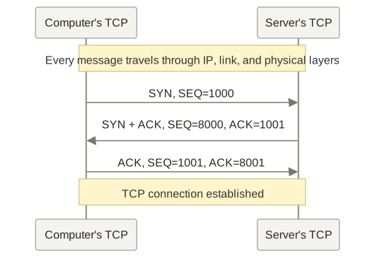
The example's handshake; every arrow travels through the lower network layers. Full-size figure · Mermaid source
TCP provides the reliable byte stream; TLS supplies authentication and encryption.
TLS handshake: authenticating and deriving keys
Full TLS 1.3 certificate handshake:
Browser                                      Server
  |--- ClientHello ---------------------------->|
  |    Supported versions, algorithms, key share |
  |                                             |
  |<-- ServerHello -----------------------------|
  |<-- Encrypted extensions, certificate,        |
  |    signature proof, Finished                |
  |                                             |
  | Validate certificate and handshake messages |
  |--- Finished ------------------------------->|
  |                                             |
|<--------- Encrypted application data ------>|- Verify the certificate hostname, trust chain, validity, and signature proof.
- Derive communication keys through ephemeral key exchange; protect later data with symmetric encryption and integrity checks.
SNI identifies the requested server name. ALPN selects the application protocol, here h2 for HTTP/2. TLS 1.3 handshake
HTTP request, server processing, and response
After HTTP/2 initialization, the request fields are as follows; the wire format uses binary frames:
:method: GET
:scheme: https
:authority: shop.example.com
:path: /products/42?color=blue
accept: text/html
accept-encoding: gzip, br
At the application level, this means:
Return the blue version of product 42's page.
I want HTML and support the indicated content compression.
Request encapsulation and Ethernet frame structure:
HTTP/2: encode the request into HEADERS and other frames
   ↓
TLS: encrypt and add integrity protection
   ↓
TCP: organize the byte stream into segments
   ↓
IP: add source and destination IP and other network fields
   ↓
Ethernet: encapsulate a frame for the gateway
   ↓
Physical: transmit as signals[Ethernet header][IPv4 header][TCP header][part of the TLS byte stream][FCS]Layer boundaries need not align. HTTP/2 frames and streams The server reverses the process:
Physical layer recovers bits from signals
   ↓
NIC and link layer recognize frames and check FCS
   ↓
IP layer processes packets addressed to this host
   ↓
TCP identifies the connection, orders and deduplicates data, and delivers contiguous bytes
   ↓
TLS verifies and decrypts
   ↓
HTTP/2 parses the request
   ↓
Web application handles /products/42?color=blueFind product 42
→ Select the blue variant
→ Read its name, price, and image address
→ Generate HTMLApplication-generated HTML:
<!doctype html>
<html lang="en">
<head>
  <meta charset="utf-8">
  <link rel="stylesheet" href="/assets/site.css">
  <script defer src="/assets/product.js"></script>
</head>
<body>
  <h1>Blue mechanical keyboard</h1>
  <p class="price">¥299</p>
  <img src="/images/keyboard-blue.webp"
       width="600" height="400" alt="Blue mechanical keyboard">
  <section id="reviews">Customer reviews</section>
</body>
</html>
The response fields might be:
:status: 200
content-type: text/html; charset=utf-8
content-encoding: br
Compressed content returns through TLS and TCP/IP. This example combines the HTTPS entry point and application; a deployment may also use a CDN or reverse proxy.
Return traffic, loss, and resource reuse
The response's public endpoints and its endpoints after reverse NAT are:
203.0.113.80:443 → 198.51.100.23:62001203.0.113.80:443 → 192.168.1.10:51514If the second segment is lost:
Sent:     segment 1, segment 2, segment 3, segment 4
Received: segment 1,            segment 3, segment 4
TCP buffers later bytes, fills the gap through retransmission, then delivers in order. Two constraints limit sending:
Does the receiver have room? → flow control and receive window
Can the network handle it?   → congestion control and congestion window
A TCP acknowledgment does not mean the page is visible. Decryption, decompression, and parsing reveal dependencies:
<link rel="stylesheet" href="/assets/site.css">
<script defer src="/assets/product.js"></script>
<img src="/images/keyboard-blue.webp">
Dependent resources can share the HTTP/2 connection:
GET /assets/site.css
GET /assets/product.js
GET /images/keyboard-blue.webpWithin one TCP/TLS connection:
CSS data → image data → JS data → image data → CSS data…Frames from different streams can be interleaved, but a gap in the TCP byte stream can still hold up multiple streams.
Browser rendering and subsequent requests
HTML produces a DOM, and CSS contributes style information before layout and painting:
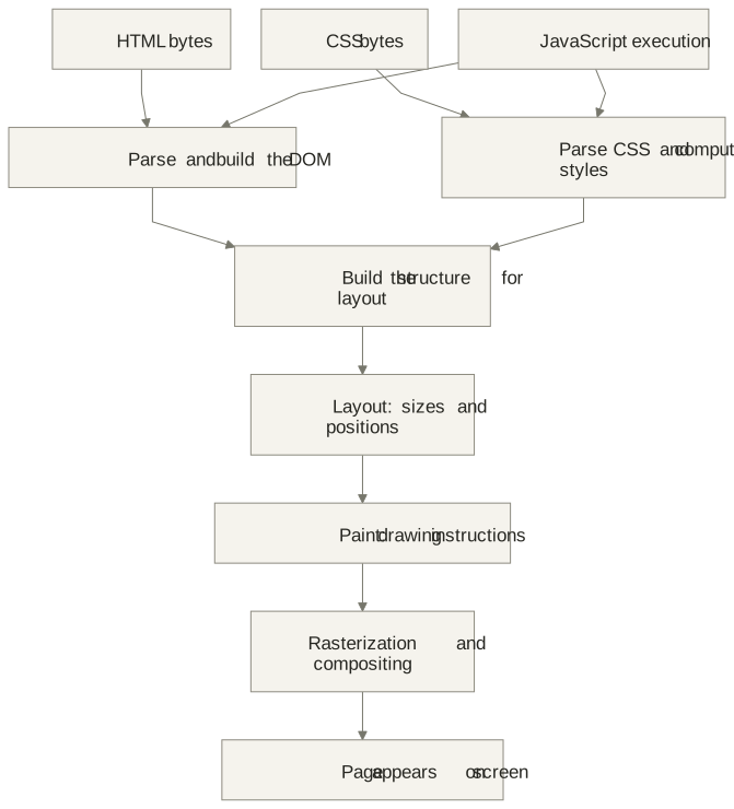
The main rendering dependencies. Full-size figure · Mermaid source
DOM describes document structure. Layout computes positions and sizes; painting generates instructions; rasterization and compositing produce and combine pixels. Downloads and rendering can overlap. Browser rendering
defer downloads without blocking HTML parsing; image dimensions reserve space; #reviews applies once the target is available.
After displaying the page, the script may request stock information:
fetch("/api/stock?product=42")
  .then(response => response.json())
  .then(data => {
    // Update the page using the stock result
  });
That request passes through the layers again and can trigger a page update:
HTTP request
→ TLS
→ TCP
→ IP
→ Data link layer
→ Physical layer
→ Server
→ Response returns
→ JavaScript updates the DOM
→ Necessary style, layout, and paint updates
First paint, DOMContentLoaded, load, and business-data readiness are separate milestones. Connections can remain reusable.
Complete sequence: tracking IP, MAC, and ports together
MAC labels are listed below; the Internet lifeline folds several router hops together. TLS and HTTP arrows still traverse that same route.
| MAC label | Interface |
|---|---|
C | Computer's network interface |
GL / GW | Home router's LAN / WAN interfaces |
I | Provider's first-hop router interface |
RD / RS | Last-hop router interface on the DNS / web server's link |
D / S | DNS / web server network interface |
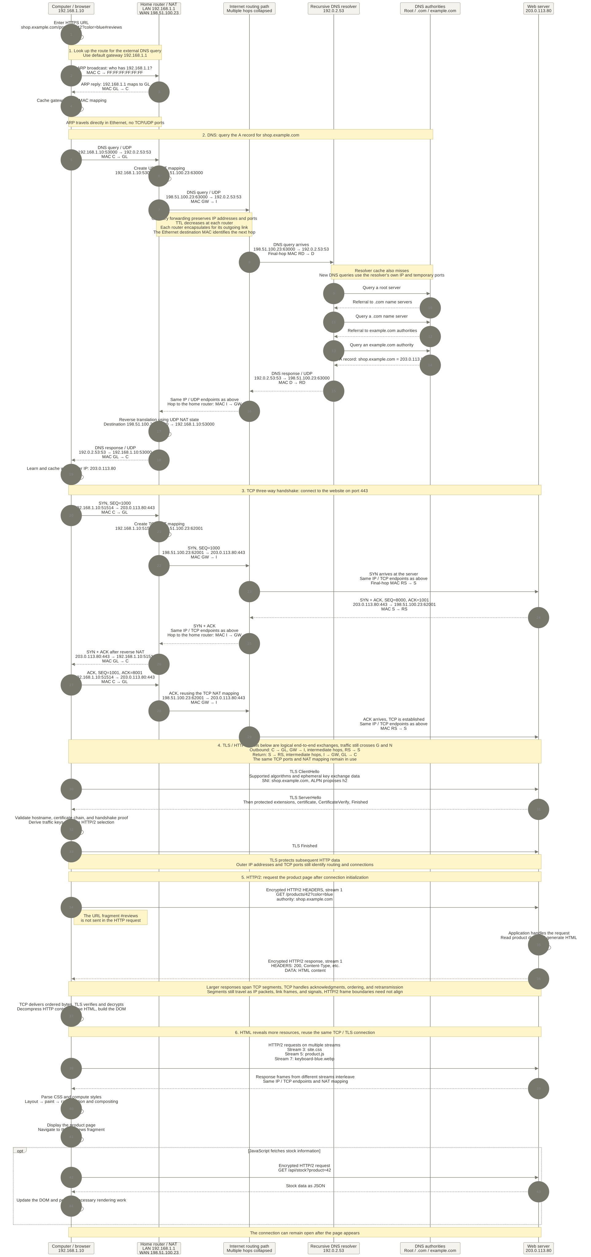
The complete sequence; open the full-size figure to read the address details. Full-size figure · Mermaid source
| Field | Computer sends | After outbound NAT | Ordinary routing | Return to the home network |
|---|---|---|---|---|
| IP | Private computer address is the source | Source becomes the router's public IP | Addresses usually stay the same; TTL decreases | Destination becomes the private computer IP |
| TCP port | Source port 51514 | Source changes to 62001 | Unchanged | Destination changes back to 51514 |
| MAC | C → GL | GW → I | Re-encapsulated at each router hop | Final hop GL → C |
UDP uses 53000 ↔ 63000; TCP uses 51514 ↔ 62001. These NAT mappings are independent.